From Figure 1.4 we see that the purpose of the link layer in the TCP/IP protocol suite is to send and receive (1) IP datagrams for the IP module, (2) ARP requests and replies for the ARP module, and (3) RARP requests and replies for the RARP module. TCP/IP supports many different link layers, depending on the type of networking hardware being used: Ethernet, token ring, FDDI (Fiber Distributed Data Interface), RS-232 serial lines, and the like.
In this chapter we'll look at some of the details involved in
the Ethernet link layer, two specialized link layers for serial
interfaces (SLIP and PPP), and the
loopback driver that's part of most
implementations. Ethernet and SLIP are the link layers used for
most of the examples in the book. We also talk about the MTU
(Maximum Transmission Unit), a characteristic of the link layer
that we encounter numerous times in the remaining chapters. We
also show some calculations of how to choose the MTU for a serial
line.
2.2 Ethernet and IEEE 802 Encapsulation
The term Ethernet generally refers to a standard published
in 1982 by Digital Equipment Corp., Intel Corp., and Xerox Corp.
It is the predominant form of local area network technology used
with TCP/IP today. It uses an access method called CSMA/CD,
which stands for Carrier Sense, Multiple Access with Collision
Detection. It operates at 10 Mbits/sec
and uses 48-bit addresses.
A few years later the IEEE (Institute of Electrical and Electronics Engineers) 802 Committee published a sightly different set of standards. 802.3 covers an entire set of
CSMA/CD networks, 802.4 covers token bus networks, and 802.5 covers token ring networks. Common to all three of these is the 802.2 standard that defines the logical link control (LLC) common to many of the 802 networks. Unfortunately the combination of 802.2 and 802.3 defines a different frame format from true Ethernet. ([Stallings 1987] covers all the details of these IEEE 802 standards.)
In the TCP/IP world, the encapsulation of IP datagrams is defined in RFC 894 [Hornig 1984] for Ethernets and in RFC 1042 [Postel and Reynolds 1988] for IEEE 802 networks. The Host Requirements RFC requires that every Internet host connected to a 10 Mbits/sec Ethernet cable:
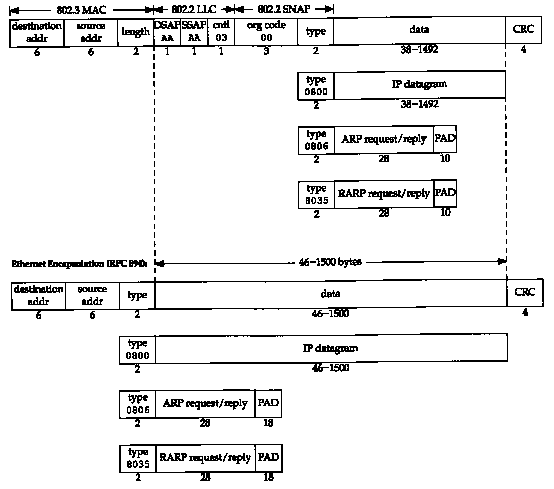
RFC 894 encapsulation is most commonly used. Figure 2.1 shows the two different forms of encapsulation. The number below each box in the figure is the size of that box in bytes.
Both frame formats use 48-bit (6-byte) destination and source addresses. (802.3 allows 16-bit addresses to be used, but 48-bit addresses are normal.) These are what we call hardware addresses throughout the text. The ARP and RARP protocols (Chapters 4 and 5) map between the 32-bit IP addresses and the 48-bit hardware addresses.
The next 2 bytes are different in the two frame formats. The 802 length field says how many bytes follow, up to but not including the CRC at the end. The Ethernet type field identifies the type of data that follows. In the 802 frame the same type field occurs later in the SNAP (Sub-network Access Protocol) header. Fortunately none of the valid 802 length values is the same as the Ethernet type values, making the two frame formats distinguishable.
In the Ethernet frame the data immediately follows the type field, while in the 802 frame format 3 bytes of 802.2 LLC and 5 bytes of 802.2 SNAP follow. The DSAP (Destination Service Access Point) and SSAP (Source Service Access Point) are both set to 0xaa. The Ctrl field is set to 3. The next 3 bytes, the org code are all 0. Following this is the same 2-byte type field that we had with the Ethernet frame format. (Additional type field values are given in RFC 1340 [Reynolds and Postel 1992].)
The CRC field is a cyclic redundancy check (a checksum) that detects errors in the rest of the frame. (This is also called the FCS or frame check sequence.)
There is a minimum size for 802.3 and Ethernet frames. This minimum requires that the data portion be at least 38 bytes for 802.3 or 46 bytes for Ethernet. To handle this, pad bytes are inserted to assure that the frame is long enough. We'll encounter this minimum when we start watching packets on the wire.
In this text we'll display the Ethernet encapsulation when we need to, because this is the most commonly used form of encapsulation.

RFC 893 [Leffler and Karels 1984] describes another form of encapsulation used on Ethernets, called trailer encapsulation. It was an experiment with early BSD systems on DEC VAXes that improved performance by rearranging the order of the fields in the IP datagram. "The variable-length fields at the beginning of the data portion of the Ethernet frame (the IP header and the TCP header) were moved to the end (right before the CRC). This allows the data portion of the frame to be mapped to a hardware page, saving a memory-to-memory copy when the data is copied in the kernel. TCP data that is a multiple of 512 bytes in size can be moved by just manipulating the kernel's page tables. Two hosts negotiated the use of trailer encapsulation using an extension of ARP. Different Ethernet frame type values are defined for these frames.
Nowadays trailer encapsulation is deprecated, so we won't show
any examples of it. Interested readers are referred to RFC
893 and Section 11.8 of [Leffler
et al.
1989] for additional details.
2.4 SLIP: Serial Line IP
SLIP stands for Serial Line IP. It is a simple form of encapsulation for IP datagrams on serial lines, and is specified in RFC 1055 [Rornkey 1988]. SLIP has become popular for connecting home systems to the Internet, through the ubiquitous RS-232 serial port found on almost every computer and high-speed modems. The following rules specify the framing used by SLIP.
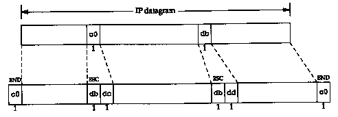
Figure 2.2 shows an example of this framing, assuming that one END character and one ESC character appear in the original IP datagram. In this example the number of bytes transmitted across the serial line is the length of the IP datagram plus 4.

SLIP is a simple framing method. It has some deficiencies that are worth noting.
Despite these shortcomings, SLIP is a popular protocol that is widely used.
The history of SLIP dates back to 1984 when Rick Adams implemented
it in 4.2BSD. Despite its self-description as a nonstandard, it
is becoming more popular as the speed and reliability
of modems increase. Publicly available implementations abound,
and many vendors support it today.
2.5 Compressed SLIP
Since SLIP lines are often slow (19200 bits/sec or below) and frequently used for interactive traffic (such as Telnet and Rlogin, both of which use TCP), there tend to be many small TCP packets exchanged across a SLIP line. To carry I byte of data requires a 20-byte IP header and a 20-byte TCP header, an overhead of 40 bytes. (Section 19.2 shows the flow of these small packets when a simple command is typed during an Rlogin session.)
Recognizing this performance drawback, a newer version of SLIP, called CSLIP (for compressed SLIP), is specified in RFC 1144 [Jacobson 1990a]. CSLIP normally reduces the 40-byte header to 3 or 5 bytes. It maintains the state of up to 16 TCP connections on each end of the CSLIP link and knows that some of the fields in the two headers for a given connection normally don't change. Of the fields that do change, most change by a small positive amount. These smaller headers greatly improve the interactive response time.
Most SLIP implementations today support CSLIP. Both SLIP links on the author's subnet (see inside front cover) are CSLIP links.
2.6 PPP: Point-to-Point
Protocol
PPP, the Point-to-Point Protocol, corrects all the deficiencies in SLIP. PPP consists of three components.
RFC 1548 [Simpson 1993] specifies the encapsulation method and the link control protocol. RFC 1332 [McGregor 1992] specifies the network control protocol for IP.
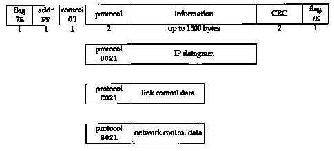
The format of the PPP frames was chosen to look like the ISO HDLC standard (high-level data link control). Figure 2.3 shows the format of PPP frames.

Each frame begins and ends with a flag byte whose value is 0x7e. This is followed by an address byte whose value is always 0xff, and then a control byte, with a value of 0x03.
Next comes the protocol field, similar in function to the Ethernet type field. A value of 0x0021 means the information field is an IP datagram, a value of 0xc021 means the information field is link control data, and a value of 0x8021 is for network control data.
The CRC field (or FCS, for frame check sequence) is a cyclic redundancy check, to detect errors in the frame.
Since the byte value 0x7e is the flag character, PPP needs to escape this byte when it appears in the information field. On a synchronous link this is done by the hardware using a technique called bit stuffing [Tanenbaum 1989]. On asynchronous links the special byte 0x7d is used as an escape character. Whenever this escape character appears in a PPP frame, the next character in the frame has had its sixth bit complemented, as follows:
The reason for doing this is to prevent these bytes from appearing as ASCII control characters to the serial driver on either host, or to the modems, which sometimes interpret these control characters specially. It is also possible to use the link control protocol to specify which, if any, of these 32 values must be escaped. By default, all 32 are escaped.
Since PPP, like SLIP, is often used across slow serial links, reducing the number of bytes per frame reduces the latency for interactive applications. Using the link control protocol, most implementations negotiate to omit the constant address and control fields and to reduce the size of the protocol field from 2 bytes to 1 byte. If we then compare the framing overhead in a PPP frame, versus the 2-byte framing overhead in a SLIP frame (Figure 2.2), we see that PPP adds three additional bytes: I byte for the protocol field, and 2 bytes for the CRC. Additionally, using the IP network control protocol, most implementations then negotiate to use Van Jacobson header compression (identical to CSLIP compression) to reduce the size of the IP and TCP headers.
In summary, PPP provides the following advantages over SLIP: (1) support for multiple protocols on a single serial line, not just IP datagrams, (2) a cyclic redundancy check on every frame, (3) dynamic negotiation of the IP address for each end (using the IP network control protocol), (4) TCP and IP header compression similar to CSLIP, and (5) a link control protocol for negotiating many data-link options. The price we pay for all these features is 3 bytes of additional overhead per frame, a few frames of negotiation when the link is established, and a more complex implementation.
Despite all the added benefits of PPP over SLIP, today there are
more SLIP users than PPP users. As implementations become more
widely available, and as vendors start to support PPP, it should
(eventually) replace SLIP.
2.7 Loopback Interface
Most implementations support a loopback interface that allows a client and server on the same host to communicate with each other using TCP/IP. The class A network ID 127 is reserved for the loopback interface. By convention, most systems assign the IP address of 127.0.0.1 to this interface and assign it the name localhost. An IP datagram sent to the loopback interface must not appear on any network.
Although we could imagine the transport layer detecting that the other end is the loopback address, and short circuiting some of the transport layer logic and all of the network layer logic, most implementations perform complete processing of the data in the transport layer and network layer, and only loop the IP datagram back to itself when the datagram leaves the bottom of the network layer.
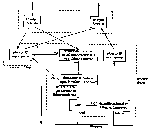
Figure 2.4 shows a simplified diagram of how the loopback interface processes IP datagrams.

The key points to note in this figure are as follows:
While it may seem inefficient to perform all the transport layer and IP layer processing of the loopback data, it simplifies the design because the loopback interface appears as just another link layer to the network layer. The network layer passes a datagram to the loopback interface like any other link layer, and it happens that the loopback interface then puts the datagram back onto IP's input queue.
Another implication of Figure 2.4 is that IP datagrams sent to the one of the host's own IP addresses normally do not appear on the corresponding network. For example, on an Ethernet, normally the packet is not transmitted and then read back. Comments in some of the BSD Ethernet device drivers indicate that many Ethernet interface cards are not capable of reading their own transmissions. Since a host must process IP datagrams that it sends to itself, handling these packets as shown in Figure 2.4 is the simplest way to accomplish this.
The 4.4BSD implementation defines the variable useloopback
and initializes it to 1. If this variable is set to 0, however,
the Ethernet driver sends local packets onto the network instead
of sending them to the loopback driver. This may or may not work,
depending on your Ethernet interface card and device driver.
2.8 MTU
As we can see from Figure 2.1, there is a limit on the size of the frame for both Ethernet encapsulation and 802.3 encapsulation. This limits the number of bytes of data to 1500 and 1492, respectively. This characteristic of the link layer is called the MTU, its maximum transmission unit. Most types of networks have an upper limit.
If IP has a datagram to send, and the datagram is larger than the link layer's MTU, IP performs fragmentation, breaking the datagram up into smaller pieces (fragments), so that each fragment is smaller than the MTU. We discuss IP fragmentation in Section 11.5.
Figure 2.5 lists some typical MTU values, taken from RFC 1191 [Mogul and Deering 1990]. The listed MTU for a point-to-point link (e.g., SLIP or PPP) is not a physical characteristic of the network media. Instead it is a logical limit to provide adequate response time for interactive use. In the Section 2.10 we'll see where this limit comes from.
In Section 3.9 we'll use the netstat command to print the MTU of an interface.
| Hyperchannel
16 Mbits/sec token ring (IBM) 4 Mbits/sec token ring (IEEE 802.5) FDDI Ethernet IEEE 802.3/802.2 X.25 Point-to-Point (low delay) | 17914 4464 4352 1500 1492 576 296 |
When two hosts on the same network are communicating with each other, it is the MTU of the network that is important. But when two hosts are communicating across multiple networks, each link can have a different MTU. The important numbers are not the MTUs of the two networks to which the two hosts connect, but rather the smallest MTU of any data link that packets traverse between the two hosts. This is called the path MTU.
The path MTU between any two hosts need not be constant. It depends on the route being used at any time. Also, routing need not be symmetric (the route from A to B may not be the reverse of the route from B to A), hence the path MTU need not be the same in the two directions.
RFC 1191 [Mogul and Deering
1990] specifies the "path MTU discovery mechanism,"
a way to determine the path MTU at any time. We'll
see how this mechanism operates after we've described ICMP
and IP fragmentation. In Section 11.6 we'll examine the ICMP unreachable
error that is used with this discovery mechanism and in Section 11.7
we'll show a version of the traceroute
program that uses this mechanism to determine the path MTU to
a destination. Sections 11.8 and 24.2 show how UDP
and TCP operate when the implementation supports path MTU discovery.
2.10 Serial Line Throughput Calculations
If the line speed is 9600 bits/sec, with 8 bits per byte, plus
I start bit and I stop bit, the line speed is 960 bytes/sec. Transferring
a 1024-byte packet at this speed
takes 1066 ms. If we're using the
SLIP link for an interactive application, along with an application
such as FTP that sends or receives 1024-byte packets, we have
to wait, on the average, half of this time (533 ms) to send our
interactive packet.
This assumes that our interactive packet will be sent across the link before any further "big" packets. Most SLIP implementations do provide this type-of-service queuing, placing interactive traffic ahead of bulk data traffic. The interactive traffic is normally Telnet, Rlogin, and the control portion (the user commands, not the data) of FTP.
This type of service queuing is imperfect. It cannot affect noninteractive traffic that is already queued downstream (e.g., at the serial driver). Also newer modems have large buffers so noninteractive traffic may already be buffered in the modem.
Waiting 533 ms is unacceptable for interactive response. Human factors studies have found that an interactive response time longer than 100-200 ms is perceived as bad [Jacobson 1990a]. This is the round-trip time for an interactive packet to be sent and something to be returned (normally a character echo).
Reducing the MTU of the SLIP link to 256 means the maximum amount of time the link can be busy with a single frame is 266 ms, and half of this (our average wait) is 133 ms. This is better, but still not perfect. The reason we choose this value (as compared to 64 or 128) is to provide good utilization of the line for bulk data transfers (such as large file transfers). Assuming a 5-byte CSLIP header, 256 bytes of data in a 261-byte frame gives 98.1% of the line to data and 1.9% to headers, which is good utilization. Reducing the MTU below 256 reduces the maximum throughput that we can achieve for bulk data transfers.
The MTU value listed in Figure 2.5, 296 for a point-to-point link, assumes 256 bytes of data and the 40-byte TCP and IP headers. Since the MTU is a value that IP queries the link layer for, the value must include the normal TCP and IP headers. This is how IP makes its fragmentation decision. IP knows nothing about the header compression that CSLIP performs.
Our average wait calculation (one-half the time required to transfer a maximum sized frame) only applies when a SLIP link (or PPP link) is used for both interactive traffic and bulk data transfer. When only interactive traffic is being exchanged, 1 byte of data in each direction (assuming 5-byte compressed headers) takes around 12.5 ms for the round trip at 9600 bits/sec. This is well within the 100-200 ms range mentioned earlier. Also notice that compressing the headers from 40 bytes to 5 bytes reduces the round-trip time for the I byte of data from 85 to 12.5 ms.
Unfortunately these types of calculations are harder to make when newer error correcting, compressing modems are being used. The compression employed by these modems reduces the number of bytes sent across the wire, but the error correction may increase the amount of time to transfer these bytes. Nevertheless, these calculations give us a starting point to make reasonable decisions.
In later chapters we'll use these serial line calculations to
verify some of the timings that we see when watching packets go
across a serial link.
2.11 Summary
This chapter has examined the lowest layer in the Internet protocol
suite, the link layer. We looked at the difference between Ethernet
and IEEE 802.2/802.3 encapsulation, and the encapsulation used
by SLIP and PPP. Since both SLIP and PPP are often used on slow
links, both provide a way to compress the common fields that don't
often change. This provides better interactive response.
The loopback interface is provided by most implementations. Access to this interface is either through the special loopback address, normally 127.0.0.1, or by sending IP datagrams to one of the host's own IP addresses. Loopback data has been completely processed by the transport layer and by IP when it loops around to go up the protocol stack.
We described an important feature of many link layers, the MTU, and the related concept of a path MTU. Using the typical MTUs for serial lines, we calculated the latency involved in SLIP and CSLIP links.
This chapter has covered only a few of the common data-link technologies used with TCP/IP today. One reason for the success of TCP/IP is its ability to work on top of almost any data-link technology.