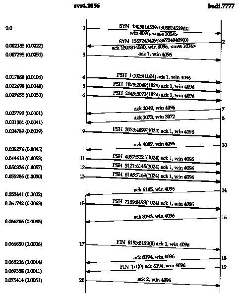
Figure 20.1 Transfer of 8192 bytes from svr4 to bsdi.
In Chapter 15 we saw that TFTP uses a stop-and-wait protocol. The sender of a data block required an acknowledgment for that block before the next block was sent. In this chapter we'll see that TCP uses a different form of flow control called a sliding window protocol. It allows the sender to transmit multiple packets before it stops and waits for an acknowledgment. This leads to faster data transfer, since the sender doesn't have to stop and wait for an acknowledgment each time a packet is sent.
We also look at TCP's PUSH flag, something we've
seen in many of the previous examples. We also look at slow start,
the technique used by TCP for getting the flow of data established
on a connection, and then we examine bulk data throughput.
20.2 Normal Data Flow
Let's start with a one-way transfer of 8192 bytes from the host svr4 to the host bsdi. We run our sock program on bsdi as the server:
bsdi % sock -i -s 7777
The -i and -s flags tell the program to run as a "sink" server (read from the network and discard the data), and the server's port number is specified as 7777. The corresponding client is then run as:
svr4 % sock -i -n8 bsdi 7777
This causes the client to perform eight 1024-byte writes to the network. Figure 20.1 shows the time line for this exchange. We have left the first three segments in the output to show the MSS values for each end.

The sender transmits three data segments (4-6) first. The next segment (7) acknowledges the first two data segments only. We know this because the acknowledged sequence number is 2049, not 3073.
Segment 7 specifies an ACK of 2049 and not 3073 for the following reason. When a packet arrives it is initially processed by the device driver's interrupt service routine and then placed onto IP's input queue. The three segments 4, 5, and 6 arrive one after the other and are placed onto IP's input queue in the received order. IP will pass them to TCP in the same order. When TCP processes segment 4, the connection is marked to generate a delayed ACK. TCP processes the next segment (5) and since TCP now has two outstanding segments to ACK, the ACK of 2049 is generated (segment 7), and the delayed ACK flag for this connection is turned off. TCP processes the next input segment (6) and the connection is again marked for a delayed ACK. Before segment 9 arrives, however, it appears the delayed ACK timer goes off, and the ACK of 3073 (segment 8) is generated. Segment 8 advertises a window of 3072 bytes, implying that there are still 1024 bytes of data in the TCP receive buffer that the application has not read.
Segments 11-16 show the "ACK every other segment" strategy that is common. Segments 11, 12, and 13 arrive and are placed on IP's input queue. When segment 11 is processed by TCP the connection is marked for a delayed ACK. When segment 12 is processed, an ACK is generated (segment 14) for segments 11 and 12, and the delayed ACK flag for this connection is turned off. Segment 13 causes the connection to be marked again for a delayed ACK but before the timer goes off, segment 15 is processed, causing the ACK (segment 16) to be sent immediately.
It is important to notice that the ACK in segments 7, 14, and 16 acknowledge two received segments. With TCP's sliding-window protocol the receiver does not have to acknowledge every received packet. With TCP, the ACKs are cumulative-they acknowledge that the receiver has correctly received all bytes up through the acknowledged sequence number minus one. In this example three of the ACKs acknowledge 2048 bytes of data and two acknowledge 1024 bytes of data. (This ignores the ACKs in the connection establishment and termination.)
What we are watching with tcpdump are the dynamics of TCP in action. The ordering of the packets that we see on the wire depends on many factors, most of which we have no control over: the sending TCP implementation, the receiving TCP implementation, the reading of data by the receiving process (which depends on the process scheduling by the operating system), and the dynamics of the network (i.e., Ethernet collisions and backoffs). There is no single correct way for two TCPs to exchange a given amount of data.
To show how things can change. Figure 20.2 shows another time line for the same exchange of data between the same two hosts, captured a few minutes after the one in Figure 20.1.
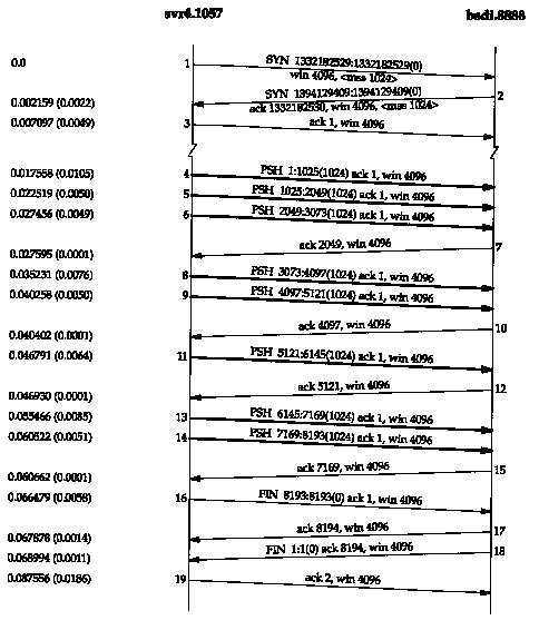
A few things have changed. This time the receiver does not send an ACK of 3073; instead it waits and sends the ACK of 4097. The receiver sends only four ACKs (segments 7, 10, 12, and 15): three of these are for 2048 bytes and one for 1024 bytes. The ACK of the final 1024 bytes of data appears in segment 17, along with the ACK of the FIN. (Compare segment 17 in this figure with segments 16 and 18 in Figure 20.1.)
Figure 20.3 shows another time line, this time from a fast sender (a Spare) to a slow receiver (an 80386 with a slow Ethernet card). The dynamics are different again.
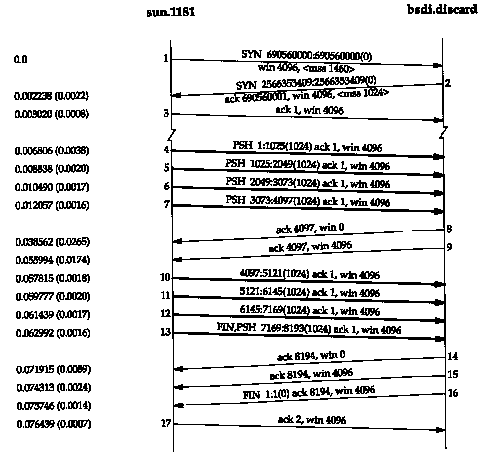
The sender transmits four back-to-back data segments (4-7) to fill the receiver's window. The sender then stops and waits for an ACK. The receiver sends the ACK (segment 8) but the advertised window is 0. This means the receiver has all the data, but it's all in the receiver's TCP buffers, because the application hasn't had a chance to read the data. Another ACK (called a window update) is sent 17.4 ms later, announcing that the receiver can now receive another 4096 bytes. Although this looks like an ACK, it is called a window update because it does not acknowledge any new data, it just advances the right edge of the window.
The sender transmits its final four segments (10-13),
again filling the receiver's window. Notice that segment 13 contains
two flag bits: PUSH and FIN. This is followed by another two ACKs
from the receiver. Both of these acknowledge the final 4096 bytes
of data (bytes 4097 through 8192) and the FIN (numbered 8193).
20.3 Sliding Windows
The sliding window protocol that we observed in the previous section can be visualized as shown in Figure 20.4.

In this figure we have numbered the bytes 1 through 11. The window advertised by the receiver is called the offered window and covers bytes 4 through 9, meaning that the receiver has acknowledged all bytes up through and including number 3, and has advertised a window size of 6. Recall from Chapter 17 that the window size is relative to the acknowledged sequence number. The sender computes its usable window, which is how much data it can send immediately
Over time this sliding window moves to the right, as the receiver acknowledges data. The relative motion of the two ends of the window increases or decreases the size of the window. Three terms are used to describe the movement of the right and left edges of the window.
Figure 20.5 shows these three terms. The left edge of the window cannot move to the left, because this edge is controlled by the acknowledgment number received from the other end. If an ACK were received that implied moving the left edge to the left, it is a duplicate ACK, and discarded.

If the left edge reaches the right edge, it is called a zero window. This stops the sender from transmitting any data.
Figure 20.6 shows the dynamics of TCP's sliding window protocol for the data transfer in Figure 20.1.
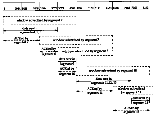
There are numerous points that we can summarize using this figure as an example.
We'll see more examples of the dynamics of the sliding
window protocol in later examples.
20.4 Window Size
The size of the window offered by the receiver can usually be controlled by the receiving process. This can affect the TCP performance.
4.2BSD defaulted the send buffer and receive buffer
to 2048 bytes each. With 4.3BSD both were increased to 4096 bytes.
As we can see from all the examples so far in this text, SunOS
4.1.3, BSD/386, and SVR4 still use this 4096-byte default. Other
systems, such as Solaris 2.2,4.4BSD, and AIX 3.2, use larger default
buffer sizes, such as 8192 or 16384 bytes.
The sockets API allows a process to set the sizes
of the send buffer and the receive buffer. The size of the receive
buffer is the maximum size of the advertised window for that connection.
Some applications change the socket buffer sizes to increase performance.
[Mogul 1993] shows some results for file transfer between two workstations on an Ethernet, with varying sizes for the transmit buffer and receive buffer. (For a one-way flow of data such as file transfer, it is the size of the transmit buffer on the sending side and the size of the receive buffer on the receiving side that matters.) The common default of 4096 bytes for both is not optimal for an Ethernet. An approximate 40% increase in throughput is seen by just increasing both buffers to 16384 bytes. Similar results are shown in [Papadopoulos and Parulkar 1993].
In Section 20.7 we'll see how to calculate the minimum buffer size, given the bandwidth of the communication media and the round-trip time between the two ends.
We can control the sizes of these buffers with our sock program. We invoke the server as:
bsdi % sock -i -a -R6144 5555
which sets the size of the receive buffer (-R option) to 6144 bytes. We then start the client on the host sun and have it perform one write of 8192 bytes:
sun % sock -i -nl -w8192 bsdi 5555
Figure 20.7 shows the results.
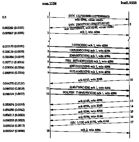
First notice that the receiver's window size is offered as 6144 bytes in segment 2. Because of this larger window, the client sends six segments immediately (segments 4-9), and then stops. Segment 10 acknowledges all the data (bytes 1 through 6144) but offers a window of only 2048, probably because the receiving application hasn't had a chance to read more than 2048 bytes. Segments 11 and 12 complete the data transfer from the client, and this final data segment also carries the FIN flag.
Segment 13 contains the same acknowledgment sequence
number as segment 10, but advertises a larger window. Segment
14 acknowledges the final 2048 bytes of data and the FIN, and
segments 15 and 16 just advertise a larger window. Segments 17
and 18 complete the normal close.
20.5 PUSH Flag
We've seen the PUSH flag in every one our TCP examples, but we've never described its use. It's a notification from the sender to the receiver for the receiver to pass all the data that it has to the receiving process. This data would consist of whatever is in the segment with the PUSH flag, along with any other data the receiving TCP has collected for the receiving process.
In the original TCP specification, it was assumed that the programming interface would allow the sending process to tell its TCP when to set the PUSH flag. In an interactive application, for example, when the client sent a command to the server, the client would set the PUSH flag and wait for the server's response. (In Exercise 19.1 we could imagine the client setting the PUSH flag when the 12-byte request is written.) By allowing the client application to tell its TCP to set the flag, it was a notification to the client's TCP that the client process didn't want the data to hang around in the TCP buffer, waiting for additional data, before sending a segment to the server. Similarly, when the server's TCP received the segment with the PUSH flag, it was a notification to pass the data to the server process and not wait to see if any additional data arrives.
Today, however, most APIs don't provide a way for the application to tell its TCP to set the PUSH flag. Indeed, many implementors feel the need for the PUSH flag is outdated, and a good TCP implementation can determine when to set the flag by itself.
Most Berkeley-derived implementations automatically set the PUSH flag if the data in the segment being sent empties the send buffer. This means we normally see the PUSH flag set for each application write, because data is usually sent when it's written.
A comment in the code indicates this algorithm is
to please those implementations that only pass received data to
the application when a buffer fills or a segment is received with
the PUSH flag.
It is not possible using the sockets API to tell
TCP to turn on the PUSH flag or to tell whether the PUSH flag
was set in received data.
Berkeley-derived implementations ignore a received PUSH flag because they normally never delay the delivery of received data to the application.
In Figure 20.1 we see the PUSH flag turned on for all eight data segments (4-6, 9, 11-13, and 15). This is because the client did eight writes of 1024 bytes, and each write emptied the send buffer.
Look again at Figure 20.7. We expect the PUSH flag to be set on segment 12, since that is the final data segment. Why was the PUSH flag set on segment 7, when the sender knew there were still more bytes to send? The reason is that the size of the sender's send buffer is 4096 bytes, even though we specified a single write of 8192 bytes.
Another point to note in Figure 20.7 concerns the three consecutive ACKs, segments 14, 15, and 16. We saw two consecutive ACKs in Figure 20.3, but that was because the receiver had advertised a window of 0 (stopping the sender) so when the window opened up, another ACK was required, with the nonzero window, to restart the sender. In Figure 20.7, however, the window never reaches 0. Nevertheless, when the size of the window increases by 2048 bytes, another ACK is sent (segments 15 and 16) to provide this window update to the other end. (These two window updates in segments 15 and 16 are not needed, since the FIN has been received from the other end, preventing it from sending any more data.) Many implementations send this window update if the window increases by either two maximum sized segments (2048 bytes in this example, with an MSS of 1024) or 50% of the maximum possible window (2048 bytes in this example, with a maximum window of 4096). We'll see this again in Section 22.3 when we examine the silly window syndrome in detail.
As another example of the PUSH flag, look again at
Figure 20.3. The reason we see the flag on for the first
four data segments (4-7) is because each one caused a segment
to be generated by TCP and passed to the IP layer. But then TCP
had to stop, waiting for an ACK to move the 4096-byte window.
While waiting for the ACK, TCP takes the final 4096 bytes of data
from the application. When the window opens up (segment 9) the
sending TCP knows it has four segments that it can send immediately,
so it only turns on the PUSH flag for the final segment (13).
20.6 Slow Start
In all the examples we've seen so far in this chapter, the sender starts off by injecting multiple segments into the network, up to the window size advertised by the receiver. While this is OK when the two hosts are on the same LAN, if there are routers and slower links between the sender and the receiver, problems can arise. Some intermediate router must queue the packets, and it's possible for that router to run out of space. [Jacobson 1988] shows how this naive approach can reduce the throughput of a TCP connection drastically.
TCP is now required to support an algorithm called slow start. It operates by observing that the rate at which new packets should be injected into the network is the rate at which the acknowledgments are returned by the other end.
Slow start adds another window to the sender's TCP: the congestion window, called cwnd. When a new connection is established with a host on another network, the congestion window is initialized to one segment (i.e., the segment size announced by the other end). Each time an ACK is received, the congestion window is increased by one segment, (cwnd is maintained in bytes, but slow start always increments it by the segment size.) The sender can transmit up to the minimum of the congestion window and the advertised window. The congestion window is flow control imposed by the sender, while the advertised window is flow control imposed by the receiver.
The sender starts by transmitting one segment and waiting for its ACK. When that ACK is received, the congestion window is incremented from one to two, and two segments can be sent. When each of those two segments is acknowledged, the congestion window is increased to four. This provides an exponential increase.
At some point the capacity of the internet can be reached, and an intermediate router will start discarding packets. This tells the sender that its congestion window has gotten too large. When we talk about TCP's timeout and retransmission algorithms in the next chapter, we'll see how this is handled, and what happens to the congestion window. For now, let's watch slow start in action.
Figure 20.8 shows data being sent from the host sun to the host vangogh.cs.berkeley.edu. The data traverses a slow SLIP link, which should be the bottleneck. (We have removed the connection establishment from this time line.)
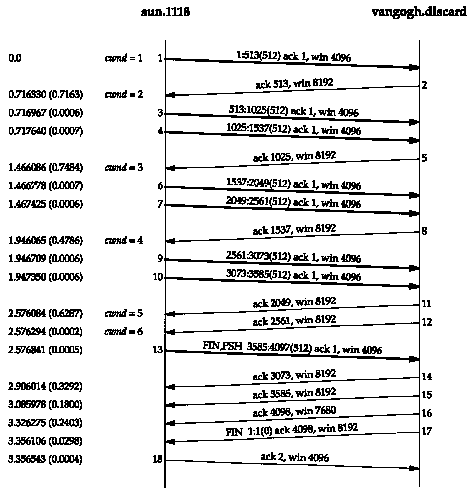
We see the sender transmit one segment with 512 bytes of data and then wait for its ACK. The ACK is received 716 ms later, which is an indicator of the round-trip time. The congestion window is then increased to two segments, and two segments are sent. When the ACK in segment 5 is received, the congestion window is increased to three segments. Although three more could be sent, only two are sent before another ACK is received.
We'll return to slow start in Section 21.6 and see
how it's normally implemented with another technique called congestion
avoidance.
20.7 Bulk Data Throughput
Let's look at the interaction of the window size, the windowed flow control, and slow start on the throughput of a TCP connection carrying bulk data.
Figure 20.9 shows the steps over time of a connection between a sender on the left and a receiver on the right. Sixteen units of time are shown. We show only discrete units of time in this figure, for simplicity. We show segments carrying data going from the left to right in the top half of each picture, numbered 1, 2, 3, and so on. The ACKs go in the other direction in the bottom half of each picture. We draw the ACKs smaller, and show the segment number being acknowledged.
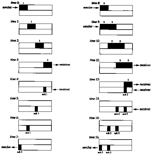
At time 0 the sender transmits one segment. Since the sender is in slow start (its congestion window is one segment), it must wait for the acknowledgment of this segment before continuing.
At times 1, 2, and 3 the segment moves one unit of time to the right. At time 4 the receiver reads the segment and generates the acknowledgment. At times 5, 6, and 7 the ACK moves to the left one unit, back to the sender. We have a round-trip time (RTT) of 8 units of time.
We have purposely drawn the ACK segment smaller than the data segment, since it's normally just an IP header and a TCP header. We're showing only a unidirectional flow of data here. Also, we assume that the ACK moves at the same speed as the data segment, which isn't always true.
In general the time to send a packet depends on two factors: a propagation delay (caused by the finite speed of light, latencies in transmission equipment, etc.) and a transmission delay that depends on the speed of the media (how many bits per second the media can transmit). For a given path between two nodes the propagation delay is fixed while the transmission delay depends on the packet size. At lower speeds the transmission delay dominates (e.g., Exercise 7.2 where we didn't even consider the propagation delay), whereas at gigabit speeds the propagation delay dominates (e.g.. Figure 24.6).
When the sender receives the ACK it can transmit two more segments (which we've numbered 2 and 3), at times 8 and 9. Its congestion window is now two segments. These two segments move right toward the receiver, where the ACKs are generated at times 12 and 13. The spacing of the ACKs returned to the sender is identical to the spacing of the data segments. This is called the self-clocking behavior of TCP. Since the receiver can only generate ACKs when the data arrives, the spacing of the ACKs at the sender identifies the arrival rate of the data at the receiver. (In actuality, however, queueing on the return path can change the arrival rate of the ACKs.)
Figure 20.10 shows the next 16 time units. The arrival of the two ACKs increases the congestion window from two to four segments, and these four segments are sent at times 16-19. The first of the ACKs returns at time 23. The four ACKs increase the congestion window from four to eight segments, and these eight segments are transmitted at times 24-31.
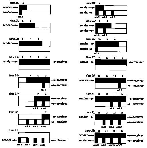
At time 31, and at all successive times, the pipe between the sender and receiver is full. It cannot hold any more data, regardless of the congestion window or the window advertised by the receiver. Each unit of time a segment is removed from the network by the receiver, and another is placed into the network by the sender. However many data segments fill the pipe, there are an equal number of ACKs making the return trip. This is the ideal steady state of the connection.
We can now answer the question: how big should the window be? In our example, the sender needs to have eight segments outstanding and unacknowledged at any time, for maximum throughput. The receiver's advertised window must be that large, since that limits how much the sender can transmit. We can calculate the capacity of the pipe as
This is normally called the bandwidth-delay product. This value can vary widely, depending on the network speed and the RTT between the two ends. For example, a Tl telephone line (1,544,000 bits/sec) across the United States (about a 60-ms RTT) gives a bandwidth-delay product of 11,580 bytes. This is reasonable in terms of the buffer sizes we talked about in Section 20.4, but a T3 telephone line (45,000,000 bits/sec) across the United States gives a bandwidth-delay product of 337,500 bytes, which is bigger than the maximum allowable TCP window advertisement (65535 bytes). We describe the new TCP window scale option in Section 24.4 that gets around this current limitation of TCP.
The value 1,544,000 bits/sec for a Tl phone line is the raw bit rate. The data rate is actually 1,536,000 bits/sec, since 1 bit in 193 is used for framing. The raw bit rate of a T3 phone line is actually 44,736,000 bits/sec, and the data rate can reach 44,210,000 bits/sec. For our discussion we'll use 1.544 Mbits/sec and 45 Mbits/sec.
Either the bandwidth or the delay can affect the capacity of the pipe between the sender and receiver. In Figure 20.11 we show graphically how a doubling of the RTT-doubles the capacity of the pipe.
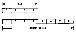
In the lower illustration of Figure 20.11, with the longer RTT, the pipe can hold eight segments, instead of four.
Similarly, Figure 20.12 shows that doubling the bandwidth also doubles the capacity of the pipe.
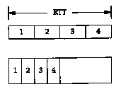
In the lower illustration of Figure 20.12, we assume that the network speed has doubled, allowing us to send four segments in half the time as in the top picture. Again, the capacity of the pipe has doubled. (We assume that the segments in the top half of this figure have the same area, that is the same number of bits, as the segments in the bottom half.)
Congestion can occur when data arrives on a big pipe (a fast LAN) and gets sent out a smaller pipe (a slower WAN). Congestion can also occur when multiple input streams arrive at a router whose output capacity is less than the sum of the inputs.
Figure 20.13 shows a typical scenario with a big pipe feeding a smaller pipe. We say this is typical because most hosts are connected to LANs, with an attached router that is connected to a slower WAN. (Again, we are assuming the areas of all the data segments (9-20) in the top half of the figure are all the same, and the areas of all the acknowledgments in the bottom half are all the same.)
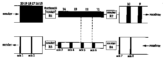
In this figure we have labeled the router R1 as the "bottleneck," because it is the congestion point. It can receive packets from the LAN on its left faster than they can be sent out the WAN on its right. (Commonly R1 and R3 are the same router, as are R2 and R4, but that's not required; asymmetrical paths can occur.) When router R2 puts the received packets onto the LAN on its right, they maintain the same spacing as they did on the WAN on its left, even though the bandwidth of the LAN is higher. Similarly, the spacing of the ACKs on their way back is the same as the spacing of the slowest link in the path.
In Figure 20.13 we have assumed that the sender did
not use slow start, and sent the segments we've numbered 1-20
as fast as the LAN could take them. (This assumes the receiving
host advertised a window of at least 20 segments.) The spacing
of the ACKs will correspond to the bandwidth of the slowest link,
as we show. We are assuming the bottleneck router has adequate
buffering for all 20 segments. This is not guaranteed, and can
lead to that router discarding packets. We'll see how to avoid
this when we talk about congestion avoidance in Section 21.6.
20.8 Urgent Mode
TCP provides what it calls urgent mode, allowing one end to tell the other end that "urgent data" of some form has been placed into the normal stream of data. The other end is notified that this urgent data has been placed into the data stream, and it's up to the receiving end to decide what to do.
The notification from one end to the other that urgent data exists in the data stream is done by setting two fields in the TCP header (Figure 17.2). The URG bit is turned on and the 16-bit urgent pointer is set to a positive offset that must be added to the sequence number field in the TCP header to obtain the sequence number of the last byte of urgent data.
There is continuing debate about whether the urgent
pointer points to the last byte of urgent data, or to the byte
following the last byte of urgent data. The original TCP specification
gave both interpretations but the Host Requirements RFC identifies
which is correct: the urgent pointer points to the last byte of
urgent data.
The problem, however, is that most implementations
(i.e., the Berkeley-derived implementations) continue to use the
wrong interpretation. An implementation that follows the specification
in the Host Requirements RFC might be compliant, but might not
communicate correctly with most other hosts.
TCP must inform the receiving process when an urgent pointer is received and one was not already pending on the connection, or if the urgent pointer advances in the data stream. The receiving application can then read the data stream and must be able to tell when the urgent pointer is encountered. As long as data exists from the receiver's current read position until the urgent pointer, the application is considered to be in an "urgent mode." After the urgent pointer is passed, the application returns to its normal mode.
TCP itself says little more about urgent data. There is no way to specify where the urgent data starts in the data stream. The only information sent across the connection by TCP is that urgent mode has begun (the URG bit in the TCP header) and the pointer to the last byte of urgent data. Everything else is left to the application.
Unfortunately many implementations incorrectly call TCP's urgent mode out-of-band data. If an application really wants a separate out-of-band channel, a second TCP connection is the easiest way to accomplish this. (Some transport layers do provide what most people consider true out-of-band data: a logically separate data path using the same connection as the normal data path. This is not what TCP provides.)
The confusion between TCP's urgent mode and out-of-band data is also because the predominant programming interface, the sockets API, maps TCP's urgent mode into what sockets calls out-of-band data.
What is urgent mode used for? The two most commonly used applications are Tel-net and Rlogin, when the interactive user types the interrupt key, and we show examples of this use of urgent mode in Chapter 26. Another is FTP, when the interactive user aborts a file transfer, and we show an example of this in Chapter 27.
Telnet and Rlogin use urgent mode from the server to the client because it's possible for this direction of data flow to be stopped by the client TCP (i.e., it advertises a window of 0). But if the server process enters urgent mode, the server TCP immediately sends the urgent pointer and the URG flag, even though it can't send any data. When the client TCP receives this notification, it in turn notifies the client process, so the client can read its input from the server, to open the window, and let the data flow.
What happens if the sender enters urgent mode multiple times before the receiver processes all the data up through the first urgent pointer? The urgent pointer just advances in the data stream, and its previous position at the receiver is lost. There is only one urgent pointer at the receiver and its value is overwritten when a new value for the urgent pointer arrives from the other end. This means if the contents of the data stream that are written by the sender when it enters urgent mode are important to the receiver, these data bytes must be specially marked (somehow) by the sender. We'll see that Telnet marks all of its command bytes in the data stream by prefixing them with a byte of 255.
Let's watch how TCP sends urgent data, even when the receiver's window is closed. We'll start our sock program on the host bsdi and have it pause for 10 seconds after the connection is established (the -P option), before it reads from the network. This lets the other end fill the send window.
bsdi % sock -i -s -P10 5555
We then start the client on the host sun telling it to use a send buffer of 8192 bytes (-S option) and perform six 1024-byte writes to the network (-n option). We also specify -U5 telling it to write 1 byte of data and enter urgent mode before writing the fifth buffer to the network. We specify the verbose flag to see the order of the writes:
sun % sock -v -i -n6 -S8192 -U5 bsdi 5555
connected on 140.252.13.33.1305
to 140.252.13.35.5555
SO_SNDBUF = 8192
TCP_MAXSEG = 1024
wrote 1024 bytes
wrote 1024 bytes
wrote 1024 bytes
wrote 1024 bytes
wrote 1 byte of urgent data
wrote 1024 bytes
wrote 1024 bytes
We set the send buffer size to 8192 bytes, to let the sending application immediately write all of its data. Figure 20.14 shows the tcpdump output for this exchange. (We have removed the connection establishment.) Lines 1-5 show the sender filling the receiver's window with four 1024-byte segments. The sender is then stopped because the receiver's window is full. (The ACK on line 4 acknowledges data, but does not move the right edge of the window.)
| 1 | 0.0 | sun.1305 > bsdi.5555: P 1:1025(1024) ack 1 win 4096 |
| 2 | 0.073743 (0.0737) | sun.1305 > bsdi.5555: P 1025:2049(1024) ack 1 win 4096 |
| 3 | 0.096969 (0.0232) | sun.1305 > bsdi.5555: P 2049:3073(1024) ack 1 win 4096 |
| 4 | 0.157514 (0.0605) | bsdi.5555 > sun.1305: . ack 3073 win 1024 |
| 5 | 0.164267 (0.0068) | sun.1305 > bsdi.5555: P 3073:4097(1024) ack 1 win 4096 |
| 6 | 0.167961 (0.0037) | sun.1305 > bsdi.5555: . ack 1 win 4096 urg 4098 |
| 7 | 0.171969 (0.0040) | sun.1305 > bsdi.5555: . ack 1 win 4096 urg 4098 |
| 8 | 0.176196 (0.0042) | sun.1305 > bsdi.5555: . ack 1 win 4096 urg 4098 |
| 9 | 0.180373 (0.0042) | sun.1305 > bsdi.5555: . ack 1 win 4096 urg 4098 |
| 10 | 0.180768 (0.0004) | sun.1305 > bsdi.5555: . ack 1 win 4096 urg 4098 |
| 11 | 0.367533 (0.1868) | bsdi.5555 > sun.1305: . ack 4097 win 0 |
| 12 | 0.368478 (0.0009) | sun.1305 > bsdi.5555: . ack 1 win 4096 urg 4098 |
| 13 | 9.829712 (9.4612) | bsdi.5555 > sun.1305: . ack 4097 win 2048 |
| 14 | 9.831578 (0.0019) | sun.1305 > bsdi.5555: . 4097:5121(1024) ack 1 win 4096 urg 4098 |
| 15 | 9.833303 (0.0017) | sun.1305 > bsdi.5555: . 5121:6145(1024) ack 1 win 4096 |
| 16 | 9.835089 (0.0018) | bsdi.5555 > sun.1305: . ack 4097 win 4096 |
| 17 | 9.835913 (0.0008) | sun.1305 > bsdi.5555: FP 6145:6146(1) ack 1 win 4096 |
| 18 | 9.840264 (0.0044) | bsdi.5555 > sun.1305: . ack 6147 win 2048 |
| 19 | 9.842386 (0.0021) | bsdi.5555 > sun.1305: . ack 6147 win 4096 |
| 20 | 9.843622 (0.0012) | bsdi.5555 > sun.1305: F 1:1(0) ack 6147 win 4096 |
| 21 | 9.844320 (0.0007) | sun.1305 > bsdi.5555: . ack 2 win 4096 |
After the fourth application write of normal data, the application writes 1 byte of data and enters urgent mode. Line 6 is the result of this application write. The urgent pointer is set to 4098. The urgent pointer is sent with the URG flag even though the sender cannot send any data.
Five of these ACKs are sent in about 13 ms (lines 6-10). The first is sent when the application writes 1 byte and enters urgent mode. The next two are sent when the application does the final two writes of 1024 bytes. (Even though TCP can't send these 2048 bytes of data, each time the application performs a write, the TCP output function is called, and when it sees that urgent mode has been entered, sends another urgent notification.) The fourth of these ACKs occurs when the application closes its end of the connection. (The TCP output function is again called.) The sending application terminates milliseconds after it starts-before the receiving application has issued its first write. TCP queues all the data and sends it when it can. (This is why we specified a send buffer size of 8192-so all the data can fit in the buffer.) The fifth of these ACKs is probably generated by the reception of the ACK on line 4. The sending TCP has probably already queued its fourth segment for output (line 5) before this ACK arrives. The receipt of this ACK from the other end also causes the TCP output routine to be called.
The receiver then acknowledges the final 1024 bytes of data (line 11) but also advertises a window of 0. The sender responds with another segment containing the urgent notification.
The receiver advertises a window of 2048 bytes in line 13, when the application wakes up and reads some of the data from the receive buffer. The next two 1024-byte segments are sent (lines 14 and 15). The first segment has the urgent notification set, since the urgent pointer is within this segment. The second segment has turned the urgent notification off.
When the receiver opens the window again (line 16) the sender transmits the final byte of data (numbered 6145) and also initiates the normal connection termination.
Figure 20.15 shows the sequence numbers of the 6145 bytes of data that are sent. We see that the sequence number of the byte written when urgent mode was entered is 4097, but the value of the urgent pointer in Figure 20.14 is 4098. This confirms that this implementation (SunOS 4.1.3) sets the urgent pointer to 1 byte beyond the last byte of urgent data.

This figure also lets us see how TCP repacketizes
the data that the application wrote. The single byte that was
output when urgent mode was entered is sent along with the next
1023 bytes of data in the buffer. The next segment also contains
1024 bytes of data, and the final segment contains 1 byte of data.
20.9 Summary
As we said early in the chapter, there is no single way to exchange bulk data using TCP. It is a dynamic process that depends on many factors, some of which we can control (e.g., send and receive buffer sizes) and some of which we have no control over (e.g., network congestion, implementation features). In this chapter we've examined many TCP transfers, explaining all the characteristics and algorithms that we could see.
Fundamental to the efficient transfer of bulk data is TCP's sliding window protocol. We then looked at what it takes for TCP to get the fastest transfer possible by keeping the pipe between the sender and receiver full. We measured the capacity of this pipe as the bandwidth-delay product, and saw the relationship between this and the window size. We return to this concept in Section 24.8 when we look at TCP performance.
We also looked at TCP's PUSH flag, since we'll always see it in trace output, but we have no control over its setting. The final topic was TCP's urgent data, which is often mistakenly called "out-of-band data." TCP's urgent mode is just a notification from the sender to the receiver that urgent data has been sent, along with the sequence number of the final byte of urgent data. The programming interface for the application to use with urgent data is often less than optimal, which leads to much confusion.
20.1 In Figure 20.6 we could have shown a byte numbered 0 and a byte numbered 8193. What do these 2 bytes designate?
20.2 Look ahead to Figure 22.1 and explain the setting of the PUSH flag by the host bsdi.
20.3 In a Usenet posting someone complained about a throughput of 120,000 bits/sec on a 256,000 bits/sec link with a 128-ms delay between the United States and Japan (47% utilization), and a throughput of 33,000 bits/sec when the link was routed over a satellite (13% utilization). What does the window size appear to be for both cases? (Assume a 500-ms delay for the satellite link.) How big should the window be for the satellite link?
20.4 If the API provided a way for a sending application to tell its TCP to turn on the PUSH flag, and a way for the receiver to tell if the PUSH flag was on in a received segment, could the flag then be used as a record marker?
20.5 In Figure 20.3 why aren't segments 15 and 16 combined?
20.6 In Figure 20.13 we assume that the ACKs come back nicely spaced, corresponding to the spacing of the data segments. What happens if the ACKs are queued somewhere on the return path, causing a bunch of them to arrive at the same time at the sender?